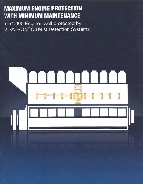
Oil mist detector for Visatron VN301 plus 2 and 4 stroke engines
Function overview:
The day- to-day mission of Schaller & Engine Protection Partner is to detect potentially harmful operating conditions in which hazardous oil mist is released as a result of bearing damage. In extreme cases, these oil mists which consist of tiny oil particles have a tendency to cause an explosion in the crankcase of the engine- Schaller oil mist detection systems represent the last reliable safeguard against such accident.
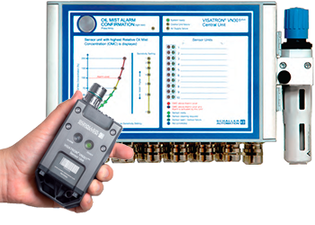
In order to respond to today’s market demands, we at Schaller & Engine Protection Partner have to put considerable thought into how we could make our product even safer and simpler.
For Schaller & Engine Protection Partner, “safety first” is not just an empty phrase or marketing slogan, it has been part and parcel of our corporate culture and practiced every day for more than 60 years. The VN301plus is based on 50 years experience in oil mist detection.
The VN301plus system consist of a central unit which up to 20 sensors (master slave version) can be connected. Each sensor monitors one crankcase compartment independently and is an standalone unit. When a sensor is replaced, the surrounding sensors ensure that the crankcase is monitors under safe conditions.
Flexibility and outstanding safety
Our hybrid cable solution offers flexible installation options and, as always , offers the benefits of our technology which is based on the Venturi principle. And what’s more, there are no wear parts or time- consuming repairs. We use fresh air to keep our sensors completely clear of dirt. This reduces maintenance overheads significantly and rules out false alarms.
The no-frills display of our central unit means you quickly gain an overview of the system status. Our products are geared towards Industry 4.0 due to our CAN and Modbus interface options.
All of our Know-how and many decades of experience has gone into making this product which means we can confidently say, ONE engine; ONE VN301plus- FOR LIFE…
The Sensor
The sensor consist of 3 parts
- Engine wall screw fitting
- Sensor
- Hybrid cable
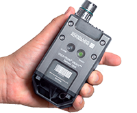
Flexibility, simplicity and reliability – this is how we control your operating cost more effectively! The engine wall screw fitting allows the sensor to be mounted on the engine and also the intake and return of the crankcase atmosphere.
The engine wall screw fitting with is flexible intake funnel is mounted from the outside. Its form prevents splash oil from being drawn in and a false alarm being triggered. We can offer you s suitable engine wall screw fitting to match the engine wall thickness.
Thanks to the rugged compact design of our sensor, it can easily be mounted on every engine. Our VN301plus can be attached to diesel/gas and dual- fuel engines- UNIVERSAL SOLUTION!.
Schaller has developed a sensor based on the Venturi principle that reduces spare parts and maintenance. It has been redesigned in order to also to achieve a significant reduction in air consumption. Keeping you operating cost under control.
The sensor is connected to the central unit using our hybrid cable. The cable supplies compressed air and power to the sensor and facilitates exchange of data with the central unit. This means that our products can communicate with Modbus or CAN Bus.
Our hybrid line allows fast installation, adapts to every engine configuration and , due to its structure , protects the cable from damage due to external factors.
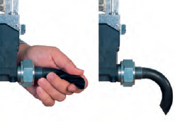
Easy installation of all types of engines!
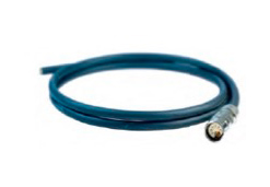 The new designed hybrid cable supplying compressed, power and signals!
Central unit
The central unit of the VN301plus system has the following functions:
- Disturbing power supply to the sensors
- Providing the operator with necessary information on system status
- Programming and adjustment
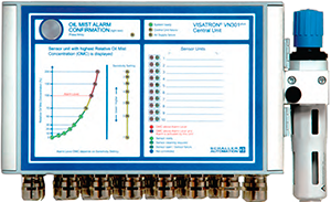
The central unit is designs to withstand extreme conditions such as vibrations or high temperature at the engine. All important information is available at a glance. Up to 10 sensor can be connected to the central unit , and up to 20 as master slave version.
Our new software makes it possible to calibrate the sensors so they are always perfectly adjusted to the engine operating conditions. Our tried and tested “floating zero algorithm” adapts to the opacity in the crankcase arising from the operation conditions and therefore prevents false alarms.
The Remote Indicator II can be connected as an option.
The central unit can communicate with modern control systems via ModBus or CAN bus. All data in the system is stored in the central unit for analysis.
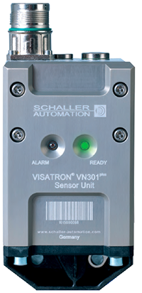
VN301plus/ VN301plus EX sensor unit
| Sensor | |
|---|---|
| Type | Sensor VN301plus |
| Communication sensor- central unit | RS485 |
| Display | Green: Ready / Red: Alarm |
| Sensor | Semiconductor Type Alcohol Sensor |
| Installation | G ¾ M27 x 1,5 |
| IP | IP 65 |
| Housing | PPA + GF, halogen- free |
| Air pressure | 2,5 bar |
| Weight | Sensor: 850 g- Engine wall screw fitting: 350 g |
| Operating temperature | 5- 70 degrees Celsius |
| Max. length of hybrid cable | 30 m |
| Atex classification (VN301plus) | II -/2G Ex OP IS IIB T4-/ GB |
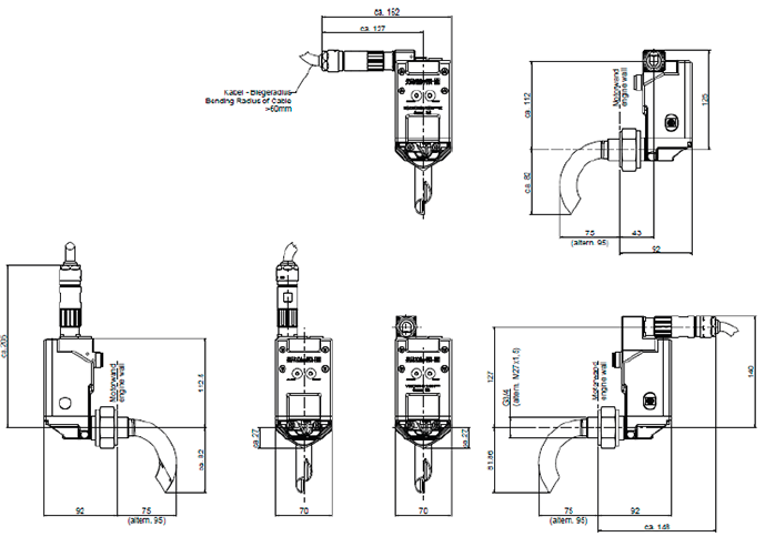
Dimensions:
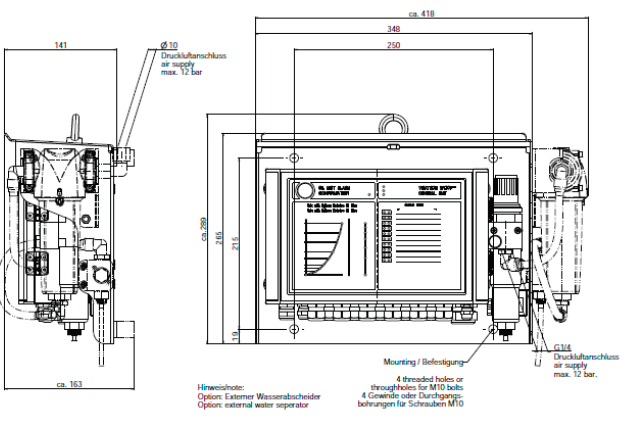
VISATRON® VN301plus central unit
| Central unit | |
|---|---|
| Type | Central unit VN301plus |
| Communication interface | CANopen/ MODBUS (RE485) |
| Installation | 4 x M10 |
| Display | Oil concentration- Alarm localization- Pressure setting- System status & Installation |
| IP | IP 65 |
| Housing | Aluminum |
| Voltage | 18- 32 VDC |
| Current | Max. 3A. |
| Air pressure | Max. 12 bar |
| Air pressure connection, pressure regulator | G ¼ |
| Weight | 7.00 kg. |
| Vibration | +/- 1,6 mm displacement or 4 G (5-100 Hz) |
| Operating temperature | +5- + 70 degrees Celsius |
| Number of sensors | 10- 20 in master slave configuration |
| Relay output | 2 x Oil Mist Alarm- 1 x Ready- 1 x Pre-alarm |
| Storage | Events: 8000 |
| Air humidity | Max. 95% |
| Communication cable to sensor | Schaller hybrid cable |
Dimensions:
Oil Mist Detector VN2020
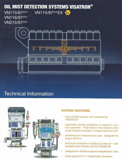
The new VN2020 Oil Mist Detector will be available during 2019! The VN2020 replaces the VN115/87plus and VN116/87plus. The VN2020 will be especially for 4- stroke engine marked. The VN301plus replaces VN215/87plus for the 2- stoke marked!
VISATRON VN2020 continuously and simultaneously evacuate crankcase atmosphere from each crankcase compartment between two main bearings.
The VN2020 use a header-suction-tube system for this purpose. The oil mist detector is positioned in the middle between two header-suction-tube sections located on the engine sides; from these sections, single-suction tubes branch off near the compartments. These tubes are considerably thinner than the header-suction tubes and they have a throttling effect. Owing to the large header-suction- tube diameter the vacuum and consequently the sample flow at each suction point remain virtually constant. The arrangement of the detector in the middle of the header-suction tube results in an optimally short sample running time in the tube system.
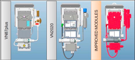
VN/87plus Re- Design to VN2020
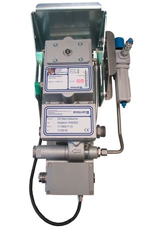
Key upgrades:
- Integrated pressure regulator including water separator
- Can be delivered with ATEX/ IECEx standard
- New designed LED panel on measuring head with separate displays for safe reading during operation
- New connection box instead of connection socket used on VN/87plus generation
- New position of Wire Break Resistors inn connection box
- REST button position directly on measuring head
- Latest SMD component and pressure sensor technology used in measuring head
- No need for scavenging air filters on VN2020- less spare parts required!
- Negative pressure to be read out directly on measuring head display- no need for u- tube manometer!
- CANopen and MODBUS RTU signals!
- New replaceable main cable between measuring head and connection box!
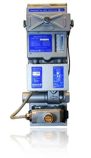
Visatron VN115/87plus
VISATRON VN 115 series continuously and simultaneously evacuate crankcase atmosphere from each crankcase compartment between two main bearings.
The VN 115 and VN 116 series use a header-suction-tube system for this purpose. The oil mist detector is positioned in the middle between two header-suction-tube sections located on the engine sides; from these sections, single-suction tubes branch off near the compartments. These tubes are considerably thinner than the header-suction tubes and they have a throttling effect. Owing to the large header-suction- tube diameter the vacuum and consequently the sample flow at each suction point remain virtually constant. The arrangement of the detector in the middle of the header-suction tube results in an optimally short sample running time in the tube system.
In the detector itself, the sample mixture of both header-suction-tube sections is conducted through an optical turbid metric channel. Subsequently, the oil mist is discharged together with the exhaust air from the wear-resistant air jet pump.
The turbidity of the crankcase atmosphere (oil mist droplets having a diameter of approx. 5 mm) is measured by optical absorption. The measuring path consists of two infrared diodes, one of them working as a transmitter and the other one as a receiver. Oil mist passing between them absorbs some of the infrared light, thereby reducing the amount of light reaching the receiver. The selected unit of measurement is % opacity [%OP]; 0% opacity means zero, turbidity, 100% OP, however, total optical absorption.
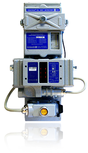
Visatron VN116/87plus
VISATRON VN 116 series as compared to the VN 115 series, is more sensitive because it has an additional differential alarm level. It compares the oil mist concentration from each side of the heeder-suction- tube section and responds if there is a difference, this being a sure sign for overheating damage in the compartment group with the higher opacity.
The differential alarm level is carried along with regard to its sensitivity relating to the 10-stage adjustment of the alarm level which is also available for VN 115. For measuring the opacity differential, the sample flows of both header-suction-tube sections are fed to the turbid metric channel one after the other by closing the respective tube sections alternately by means of reed valves.
The microprocessor saves both opacity values and executes the opacity comparison (damage check). In-home position both valves are open. They only become operative if the compound opacity from both header-suction-tube sections exceeds the sensitive threshold for starting the damage check. This will trip an alarm if the decisive differential alarm level is being exceeded. At the same time, it is indicated in which compartment group the damage has occurred.
Oil mist is explosive from a concentration of 50 mg of atomized oil in 1 liter of air = 40% OP, the ignition temperature of approx. 500 C. It is important that the opacity value exponentially depends, upon the oil mist concentration, i. e. it is already very high in case of minor turbidity. Therefore, turbidity measurement with the header-suction-tube system can also reach a high sensitivity (e.g. 0,5% OP= 0,1 mg/l of oil mist) from a damaged compartment mixed with crankcase atmosphere from the other compartments is diluted in the header-suction tube. In case of medium speed trunk-piston engines, the compartment volumes are relatively small compared with the crankcase of crosshead engines so that the oil mist has developed from overheating damage will rapidly result in a higher concentration.
VISATRON VN215/87plus
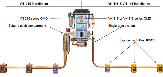
VISATRON VN215/87plus, operates in the same way as the VN 116/87plus as far as the tripping of an alarm is concerned, however, it is able to additionally indicate the suction point with the highest opacity and thus the compartment in which the overheating damage has occurred. Unlike the other types, the VN 215 series has a single-suction-tube system, each compartment being connected by a separate tube to a valve box designed for 10 suction lines. All procedures are similar to those of type VN 116 series.
Normally, the compound opacity of the oil mist from all compartments will continuously be measured. If the opacity exceeds the damage check starting threshold a damage check will be executed. lf the differential alarm level is exceeded, an alarm causing the automatic stop of the machine or a speed reduction will immediately be tripped. In contrast to the type VN 116 series, a search run will be continued. By closing the valves of certain compartment groups according to an iteration procedure and by an opacity comparison, the single-suction line can finally be determined which is supplied with oil mist from the compartment in which the overheating damage has occurred. For damage indication on the detector, the position of the valve which is still left open is used for indicating the damaged compartment.
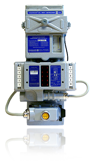
In order to meet the high mechanical and electrical demands and to take account of the most limited space at the engine, all VISATRON oil mist detectors are constructed as packaged units by using aluminum cast, with the wear-resistant air-jet jump, the vibration-isolated base plate for the metal-clad measuring unit with plug and socket connection as well as the electrical and pneumatically connections being erected on a solid cast iron plate. The suction tubes on the left and right sides are connected to the valve box by two molded rubber flanges having no threads. The use of the particularly advantageous siphon assembly likewise allows a connection of the tubes of the siphon blocks without any threads.
All subassemblies including the valve box are provided with plug and socket connections and can, if necessary, be exchanged without the tubes at the engine having to be dismounted.
Visatron pressure reducer. Part no. 10001
The Visatron pressure regulator is an important part combined with the oil mist detector. The device secures a safe operation of the airflow supplied to the oil mist detector. The system is build up with a safety unit that secures the airflow not to pass over max. 90,00 mm WC. The system also provides clean air to the oil mist detector threw the filter system. The pressure reducer is used for all VISATRON oil mist detectors.
Benefits:
- The pressure reducer secures stabile and clean air to the oil mist detector
- Air filter installed in the safety unit
- Solid construction with long life time
- Complete repair/ maintenance kit available
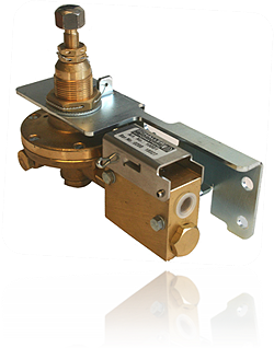
Technical description of device:
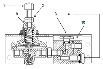
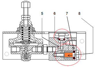
** On devices delivered after 01.2012, setting screw is not presented – as the setting point is set by manufacturer!
Repair kit for pressure reducer. P/n.: 11068, contains following parts:
- 1 x The complete adjusting device incl. adjustment screw
- 1 x Filter for pressure reducer. P/n: 10002
- 1 x O- ring for bronze filter screw. P/n: 10003
- 1 x O- ring for throttle set screw. P/n: 10004
- 1 x O- ring for throttle set screw- small. P/n: 10679
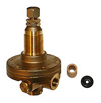
| Part no: | Product: | Other information: |
|---|---|---|
| 10001 | Pressure reducer | Complete reducer with safety device |
| 10002 | Filter for pressure reducer | Shown as no. 8 under “Technical description” |
| 10003 | O- ring for bronze filter screw | Shown as no. 7 under “Technical description” |
| 10004 | O- ring for throttle set screw | Shown as no. 6 under “Technical description” |
| 10679 | O- ring for throttle set screw- small | Shown as no. 5 under “Technical description” |
| 11068 | Repair kit for pressure reducer | See: “Repair kit for pressure reducer” |
Sampling Funnels
If there is too much oil in the oil mist detector and the pipe system, you need to check if there are sampling funnels installed in the crankshaft room on every suction point.
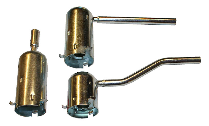
A sampling funnel is an oil labyrinth where the large oil droplets are filtered away, and just the small oil mist droplet will pass. It is necessary to install long type sampling funnels if the pipe system does not have the 2-4 % of an angel.
There is two different main types of sampling funnels: the short type (normally used for new engines) and long type sampling funnel (normally used for engines with age over 8 years). Please contact us for specified type for your engine!
Oil Separators
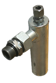
Oil draining device. Part no. 11164
The oil draining device is used to drain back oil laying in the pipe system from the engine to the oil mist detector.
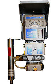
Oil separator. Part no. 11163
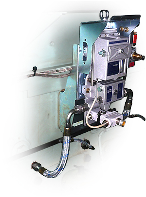
This oil separator unit drains / returns the oil coming out from the oil mist detector exhaust port. The oil separator unit is the solution to eliminate the problem with oil spills around the engine and to avoid that oil mist remains in the engine room atmosphere.
Installation kit/ Pipe system
Swift Marine Tech Services is your best partner for complete installations of oil mist detection systems for India & Bangladesh regions.
For installation, projects, we require no specification or drawings of the engine – only images and information about engine wall dimensions, pipe connections, existing OMD pictures etc. will be enough to review your exact requirements which is being verified & certified by Schaller design engineers before conducting any installation projects.
The brackets and bending of the tube takes place on the installation site.
Our Service Personnel are recognized worldwide for its on-site installations. All piping systems are delivered with long-type sampling funnels.
We maintain huge stock of Schaller genuine spares and complete systems in Mumbai and Singapore.
Digital u- tube manometer. Part no. 100138
The digital u- tube manometer is easy to use for checking the negative pressure in your oil mist detector. The digital u- tube manometer shows the value in mmH2O- the same as mmWC. Recommended pressure is 60,00 mmWC/ mmH2O.
Benefits:
- Easy to use
- Do not require water to be filled in
- Solid construction with long life time
- Accurately and measuring
How to use:
- Before starting the procedure- stop the engine! Turn off the air pressure on the pressure regulator unit.
- Unscrew the plug (part no. 10083) on the inspection cover located on the measuring head. Install the quick connection (part no. 10053.),
- Press
 on the digital u- tube manometer- then 0,0 mmH2O will be indicated in the display.
 - Press in the main connection into the quick connection, and start to adjust the adjusting screw on the pressure reducer until the display show 60,00 mmH2O on the digital u- tube manometer.
- When this is done, disconnect the digital manometer from the oil mist detector- the negative pressure is now adjusted.
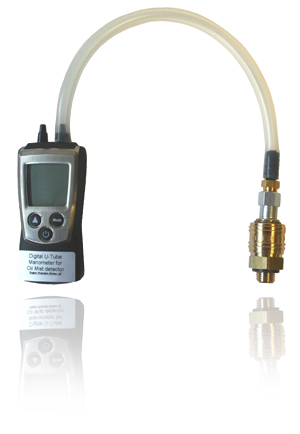
| Part no: | Product: | Other information: |
|---|---|---|
| 100138 | Digital u- tube manometer | Complete manometer without adapter kit |
| 10053 | Quick connection for u- tube manom | Quick connection connected to inspection cover on OMD! |
| 100139 | Adapter kit | Adapter connections incl. flexible pipe! |
| 100140 | Batteries for digital u- tube manometer | 2 x 1.5 V AAA batteries. |
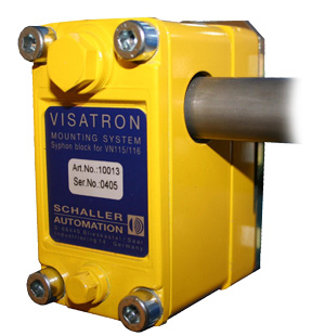
Syphon block for VN180, VN 115 & VN 116 series. Part no. 10013
Not all engines allow installations where the main tube has recommended 2- 4 % angel. The reason why we recommend the 2- 4 % angel on the main tube is based that collected oil inside the tubing system is drained back to the crankcase. The syphon blocks are specially made for oil mist detector installations where the main tubes are installed in horizontal position. The syphon blocks are designed to let the oil mist go through the pipe system and let the oil and oil droplets be drained back to the crankcase. The design makes the installation of pipes quick and easy.
Benefits:
- Easy installation
- No need for main pipes system with 2- 4 % angel
- Easy to maintenance
Difference between VN 215 & VN 115/ VN 116 installation:
Accessories:

| 1 | Syphon block VN 180 | Part no.: 10013 |
| 2 | Rubber insert for syphon block VN180 | Part no.: 10095 |
| 3 | Mounting plate for syphon block VN180 | Part no. 10089 |
| 4 | O- ring for siphon block VN 115 & VN 116 | Part no.: 365287 |
| 5 | Plug for siphon block VN 180 | Part no.: 340375 |
Driving air conditioning kit. Part no. 272213
In case of a non-optimal driving air quality to the oil mist detector, the driving air conditioning kit (P/n: 272213) may help you get rid of failing to measure heads, being activated eg. by failure LED no. 14- negative pressure/ airflow too low. The water separator device eliminates the risk of water making technical problems inside the pressure reducer, measuring head and the ejector pump. The system is specially made to rise up the air quality to a high stabile level.
Benefits:
- For longer lasting fresh air filter/ scavenging air filter (P/n: 10042) lifetime
- Makes independ of onboard air quality
- Automatic de- oiling/ watering system as option
Technical overview/description of device:
- Flexible tube for connection to inlet compressed air
- Draining for water/ oil
- Protection cover. P/n: 10753**
- Connection pipe between separator unit and pressure reducer. P/n: 10001
- Separator device
- Pressure reducer. P/n: 10001**
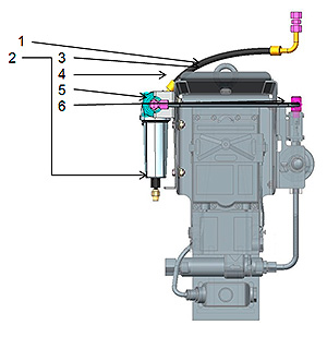
** The driving air conditioning kit requires protection cover (P/N: 10753) and pressure reducer (P/n: 10001) for installation!
| Part no: | Product: | Other information: |
|---|---|---|
| 272213 | Driving Air Conditioning Kit | Complete kit including point no.: 1,2, 4 & 5 |
| 10753 | Protection cover | The driving air conditioning kit requires protection cover for installation. |
| 10001 | Pressure reducer | The driving air conditioning kit requires pressure reducer for installation. |
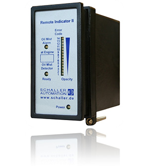
Remote indicator II. Part no. 11506
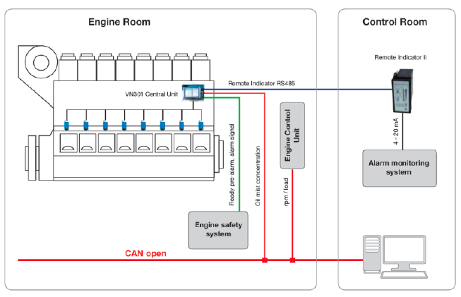
The remote indicator II allows the safe remote monitoring of the oil mist concentration from outside the engine room e.g. from the engine control room.
In use with a VN93 or VN87plus, it is possible to monitor the relative opacity and the state of one OMD device similar to the OMD display. The connection to the VN/93 and VN/87plus units is realized by an RS485 two-wire bus.
Optional the remote indicator II can be connected to a VN87-EMC unit. This connection to theVN/87-EMC is realized as a two-wire analog interface. If a VN/87-EMC is connected to the remote indicator II, the device monitors only the oil mist concentration and not the state of the OMD device.
Benefits:
- Full overview of “real-time” measurement of oil mist concentration
- Secures personnel’s situation in cases of high oil mist alarm
- Meet’s the IACS UR 10.11 requirement
- Easy to install
Accessories:
| Remote indicator unit II | Part no. 11506 |
| Connector FK-MCP 1,5/12-STF-3,81* | Part no. 11507 |
| Grommet | Part no. 11501 |
| Network terminator | Part no. 11502 |
| Front glass plate for horizontal installation | Part no. 11510 |
| Front glass plate for vertical installation | Part no. 11511 |
| Jumper | Part no. 11512 |
| 5 x label engine type | Part no. 11508 |
Connection diagram for remote indicator II to VN/93 & VN/87plus:
| Name: | Pin- no. Remote indicator II: | Connected to pin- no. on oil mist detector: |
|---|---|---|
| RS485 A | 1 | Pin 13 of VN/93 and VN/87plus |
| RS485 B | 2 | Pin 11 of VN/93 and VN/87plus |
| RS485 GND | 3 | — |
| Optional current interface + | 4 | — |
| Optional current interface – | 5 | — |
| VN/87- PWM interface + | 6 | — |
| VN/87- PWM interface – | 7 | — |
| 4- 20 mA Output + (max. 220 ohm) | 8 | Optional to alarm monitoring system |
| 4- 20mA Output – | 9 | Optional to alarm monitoring system |
| Earth | 10 | Earth & data cable shield |
| Power supply GND | 11 | 0 Volts |
| Power supply 24 Volts | 12 | +24 Volts DC |
Connection diagram for remote indicator II to VN/87EMC:
| Name: | Pin- no. Remote indicator II: | Connected to pin- no. on oil mist detector: |
|---|---|---|
| RS485 A | 1 | — |
| RS485 B | 2 | — |
| RS485 GND | 3 | — |
| Optional current interface + | 4 | — |
| Optional current interface – | 5 | — |
| VN/87- PWM interface + | 6 | Pin 9 of VN/87 EMC |
| VN/87- PWM interface – | 7 | Pin 10 of VN/87 EMC |
| 4- 20 mA Output + (max. 220 ohm) | 8 | Optional to alarm monitoring system |
| 4- 20mA Output – | 9 | Optional to alarm monitoring system |
| Earth | 10 | Earth & data cable shield |
| Power supply GND | 11 | 0 Volts |
| Power supply 24 Volts | 12 | +24 Volts DC |

